


Печать теста «kickstarter-autodesk-3d-master», неявные особенности тестовой модели, оказывающие влияние на прохождение теста, уточнение тестовой модели и полученные результаты печати теста на 3д принтере Лад-1.0.
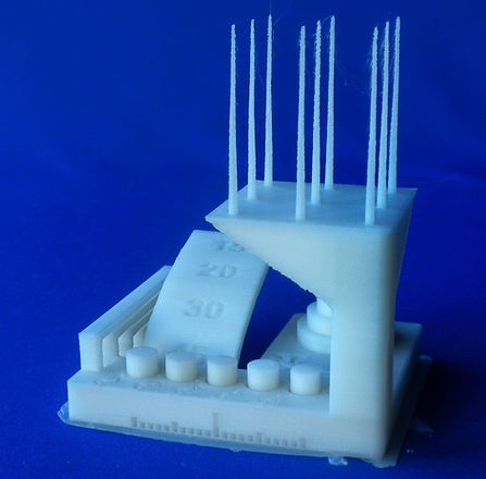
Этот тест интересен количественной оценкой возможностей принтера. Тест выполнялся два раза.
Тест №1 выполнялся при следующих настройках:
-
Материал - АБС неокрашенный от #3DPlast.
-
Диаметр сопла 0,3 мм.
-
Высота слоя 100 мкм.
-
Температура печати 240 гр.С.
-
Скорость по умолчанию 40 мм/с.
-
Скорость наружных периметров 20 мм/с.
По результатам была получена оценка 27 из 30.
В ходе выполнения теста была выявлена особенность
построения платформы теста 2 (точности подачи пластика) оказывающая влияние на печать, но не влияющая на оценку теста. Выяснилось, что особенности модели не позволяют слайсеру S3D правильно обработать основание платформы, что вызывает провисание периметра (особенно при печати относительно тонкими слоями) и сброс некоторой части петель формируемой на нем опорной поверхности.
Для устранения ненужных сложностей при выполнении теста, в геометрию модели были внесены необходимые изменения. Затем, после установки сопла диаметрам 0,4 мм и увеличения высоты слоя до 200 мкм, был выполнен ещё один тест (№2). По результатам была получена оценка 25,5 из 30.
Тест №1.
-
Точность размеров - 5
-
Точность подачи пластика - 5
-
Точность зазоров - 4
-
Построение навесов - 3
-
Построение мостов - 5
-
Резонансы XY - 2,5
-
Неравномерность Z - 2,5
Итоговая оценка - 27


Причины �возникновения сложностей при печати площадки теста 2.
Сравним построение мостов (тест 5) и площадки теста 2:
При построении моста (показан в верхней части рисунка),
-
между двумя опорами печатаются периметры,
-
также, между двумя опорами печатается опорная поверхность моста,
-
поверх сформированной опорной поверхности печатаются следующие слои модели.
При построении площадки (показана в нижней части рисунка),
-
периметры печатаются по контуру будущей опорной поверхности,
-
опорная поверхность печатается между сформированными ранее опорами и висящим в воздухе тонким периметром. При такой длине тонкий периметр под тяжестью укладываемых на него петель опорной поверхности провисает и часть петель недостаточно свариваются между собой, не привариваются к податливому тонкому периметру и сбрасываются,
-
без нормально сформированной опорной поверхности, последующие слои ложатся беспорядочно и формируют площадку для теста только за счет общей её толщины.

Изменения тестовой модели для исправления опорной площадки теста 2
Так как сама опорная площадка не влияет на оценку теста, в модель был добавлен периметр площадки высотой 1,5 мм для нормального формирования площадки теста 2.
Результат показан на рисунке.
Изменённая модель здесь:
Тест №2.
-
Точность размеров - 5
-
Точность подачи пластика - 2,5
-
Точность зазоров - 4
-
Построение навесов - 4
-
Построение мостов - 5
-
Резонансы XY - 2,5
-
Неравномерность Z - 2,5
Итоговая оценка - 25,5

