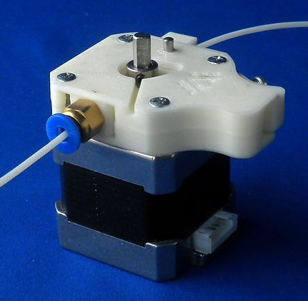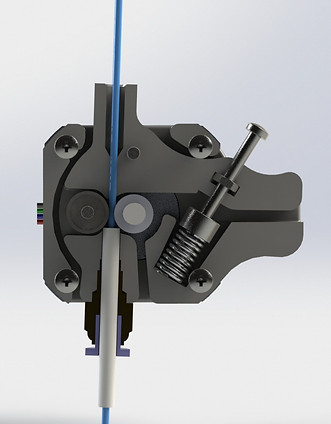
Extruder 1

Model: Extruder1
The extruder is the first thing I changed on a prototype of my 3D LAD-1.0 printer.
Bought on "Ali" MK8 obviously did not cope. The clacks of a stepper motor forced the temperature of the nozzle to rise above the optimum and reduce the performance of the printer. Pro printing with a nozzle of 0.3 mm could not even be considered. The 52 N * cm torque of the 17HS8401 stepper motor was not enough for a gear roller with a diameter of 11 mm. In addition, there was a tendency to the filament wringing due to the large distance from the toothed roller to the inlet of the bowden tube.
Therefore, I decided to make an extruder with a reduced roller having a diameter at the tops of the teeth of 7.5 mm, which promised an increase in the force by almost 1.5 times.

In addition, while remaining within the framework of the RepRap concept, I decided to ensure a minimum load on the bearings of the stepping motor in order to increase their service life, for which the shoulder of force on the shaft should be made as small as possible.
At the same time I set the task of eliminating filament wringing, but retaining the adjustment of the roller pressure and the convenience of manual filling the filament into the extruder.
Further “Johnny, make a montage” © and that's what happened:
Extruder 1 can be assembled in several versions:
-
With a bowden tube hold on the ledge of the PC4-M6 pneumatic connector and with an additional guide bushing inserted between the feed roller and the pneumatic connector.
-
With the bowden tube passing through the hole drilled to a diameter of 4.1 mm in the pneumatic connector.
-
With one-piece lever and thread M3 cut in plastic for the installation of an adjusting screw.
-
With a lever assembled from two halves, with a steel nut for installing an adjusting screw.


Purchased parts:

Sleeve guide Drawing (PTFE tube D4 d2 L10):

Printed parts.After printing, holes are drilled to install the axis of 3 mm in diameter, in the lever are cut threads M3 under for adjusting screw and threads M6 for the pneumatic connector:
A variant of the lever, glued together from two halves and with M3 nut, is printed without supports:


Lever Assembly:

Extruder assembly, with the cover removed:

This extruder has worked for me more than 1000 hours no problem. The design proved to be balanced, the traction ability of the engine and the toothed roller were almost equal. Filament wringing did not occur, refueling is quite convenient.
As a result - only 20 grams of filament and the problem is solved.
Link to the model is at the beginning of the article.


